Starting Systems
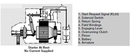
Purpose of the Starting System
The purpose of the starting system is to convert chemical energy stored in the battery into electrical energy, then into mechanical energy in the starter motor. This mechanical energy is then transferred through gears and drives from the starter motor to the engine flywheel.
After the transfer and conversion of all this energy the engine flywheel begins to rotate. The rotation must be of sufficient speed to allow the engine to form the combustible air-fuel mixture required for starting. It must be maintained during initial combustion long enough until the engine can sustain operation.
To accomplish this, a starter or cranking motor is used.
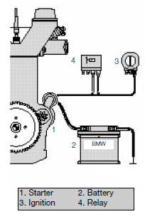
The starting system consists of the following components:
• Battery
• Ignition Switch
• Starter Motor Assembly
• EWS (if equipped)
• Starter Safety Switch
• Cables and Wiring Harness
System Components
Battery
The Battery is the primary EMF source in the automobile. The automotive battery is an electro-mechanical device that provides the potential difference (voltage). The battery does not store electrical energy. It stores chemical energy that is converted to electrical energy as it discharges.
All energy for starting the car is drawn from the battery. State-of-charge, and capacity of the battery are important factors in the ability of the engine to start, especially in cold and harsh conditions.
Ignition Switch
The Ignition Switch provides a request to the starting system to engage the starter motor. This request is handled differently depending on the year of the vehicle and particular systems the vehicle is fitted with.
In non EWS systems the ignition switch provided power directly to the starter solenoid or a starter relay. Beginning with EWS I the start request (KL50) is passed to an Immobilizer control module or an EWS module (EWS II/III).
On vehicles with one touch starting the KL50 signal is passed to the DME.
Starter Motor Assembly
The Starter Motor Assembly is a DC motor which uses the interaction of magnetic fields to convert electrical energy into mechanical energy.
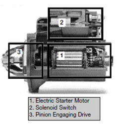
The starter motor assembly consists of:
• Electric Starter Motor
• Solenoid
• Pinion Engaging Drive
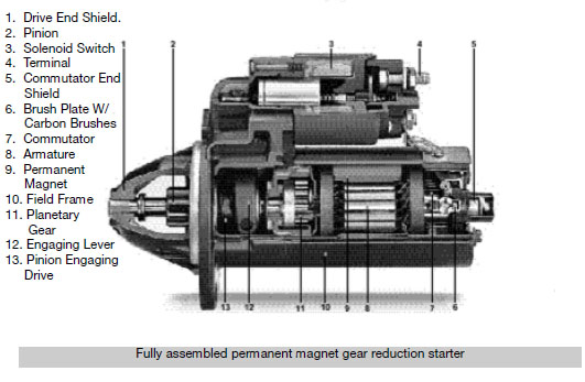
Electric Starter Motor
The Starter Motor provides the mechanical energy to rotate the engine through a direct or a gear reduction drive.
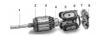
The major components of the starter motor are:
• Armature Shaft (1)
• Armature Winding (2)
• Armature Stack (3)
• Commutator (4)
• Poles Shoes (5)
• Field Coil (6)
• Carbon Brushes (7)
• Brush Holder (8)
Armature
The Armature assembly is comprised of the armature shaft, armature winding, armature stack and commutator. Thin iron stampings are laminated together to form the stack or core. The slots on the outside of the laminations hold the armature windings. The windings loop around the core and are connected to the commutator. Each commutator segment is insulated from the adjacent segments. The commutator may have up to 30 segments. A steel shaft is insert in the center hole of the laminations with the commutator insulated from the shaft.

Field Coils
There are two types of field coils:
• Electromagnetic
• Permanent magnet
Electromagnetic
Wire ribbons or coils wrapped around a pole shoe, attached to the inside of the starter housing. The iron pole shoes and the iron starter housing work together to increase and concentrate the strength of the field coils. When current flows thought the field coils strong electromagnetic fields with North and South poles are created.
Permanent
Multiple permanent magnets manufactured from an alloy of boron, neodymium and iron are positioned in the starter housing. Use of permanent magnets allow for the elimination of the field circuit and windings and realize a 50% weight savings.
Brushes
Brushes are electrically conductive sliding contacts, usually made of copper and carbon. The brushes make contact with the commutator and as the starter begins to rotate the brushes reverse the flow of current to the armature. Starter brushes carry the full flow of current through the motor.
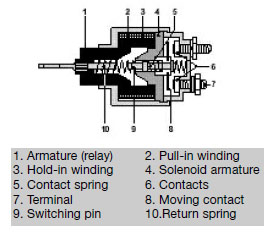
Solenoid
The Solenoid assembly is an integral part of the starter and is actually a combined relay and engagement solenoid.
The solenoid has two functions:
• Pushing the pinion forward so that it engages in the ring gear of the engine.
• Closing the moving contact, providing the main current path for the starter.
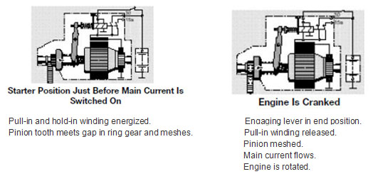
The solenoid has two windings.
• Pull-in winding • Holding-in winding
Both windings are used to draw in the plunger and engage the pinion, only the hold-in winding is used to hold the plunger in position.
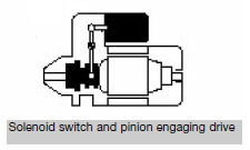
Pinion Engaging Drive
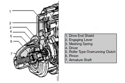
The starter’s end shield assembly contains the Pinion Engaging Drive with pinion, overrunning clutch, engagement lever and spring. The drive mechanism is responsible for coordinating the thrust motion of the solenoid switch and the rotary motion of the electric starter motor and transferring them to the pinion.
The starter engages the ring gear on the flywheel by means of the pinion. A high conversion ratio of pinion teeth to flywheel teeth (between 10:1 and 15:1) make it possible to overcome the high cranking resistance of the engine using a relatively small but high speed starter motor.
As soon as the engine starts and accelerates past cranking speed, the pinion must automatically disengage in order to protect the starter. For this reason, the starter incorporates an overrunning clutch.
Starter Drives
Conventional Drive
In a Conventional Drive starter the pinion gear is located directly on the armature shaft.
The pinion and overrunning clutch form the driver assembly.
The driver assembly rides on a helical spine on the armature shaft so that when the driver is thrust by the solenoid, a combined axial and rotary motion occurs which greatly facilitates the meshing of the pinion.
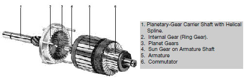
Gear Reduction Drive
In their design and function, Gear Reduction Drives are much the same as conventional drive starters. The main difference in the gear reduction drive starter is a planetary gear set added between the field frame and the drive end shield. This design allows for the use of smaller and lighter starters.
Overrunning Clutch
In all starter designs the rotary motion is transmitted via an Overrunning Clutch. The overrunning clutch allows the pinion to be driven by the armature shaft (or planetary gear set), however it breaks the connection between the pinion and the armature shaft as soon as the accelerating engine spins the pinion faster than the starter.
The overrunning clutch is located between the starter motor and the pinion and prevents the starter motor armature from being accelerated to an excessive speed when the engine starts.
EWS
The EWS system(s) is designed to provide electronic anti-theft protection for the vehicle through the use of coded keys and coded data communication between the EWS and the engine control module. The starter and engine control module are locked out until a properly coded key is recognized and the proper code is established between the EWS and the engine control modules.
Starter Safety Switch
The Starter Safety Switch is part of the transmission range switch on automatic transmission vehicles and a clutch switch on manual transmission vehicles (beginning MY 1997).
The purpose of the switch is to prevent engine start-up with the vehicle in gear or the clutch not depressed. On vehicles with EWS, this signal is sent directly to the EWS module for processing.
Cable and Wiring Harness
Cables to the starter from the battery must carry large amounts of current. The wiring harness from the ignition switch and/or EWS carry little current as they are control signals to a relay or starter solenoid. Minimum voltage drop in starter cables is necessary to ensure sufficient starter speed and torque.
Starting System Principle of Operation
Electric Starter Motor
The Electric Starter Motor converts electrical current into rotary motion. In doing so it converts electrical energy into mechanical energy. The interaction of two magnetic fields produces this rotational force.
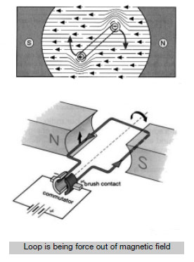
The field coils (either electromagnetic or permanent) located in the housing produce magnetic flux lines. Within the stationary field coils is the armature, a loop of wire (a conductor) with one end connected to B+, the other to B-. When current is applied to the armature flux lines circle the loop in one direction on one side and in the opposite direction on the other side. The interaction of the flux lines on the armature and the flux lines from the field coil cause the armature to rotate.
The armature will only rotate to the point where the magnetic force is equal on both sides.
(Armature 90o to magnetic flux lines of field) For the armature to continue to rotate, the polarity or direction of current flow must be reversed.
Through the brushes and the commutator, the current flow is reversed as the magnetic forces become equal, causing the armature to continue to rotate.
This constant reversal of current flow in the armature provides continual rotation.
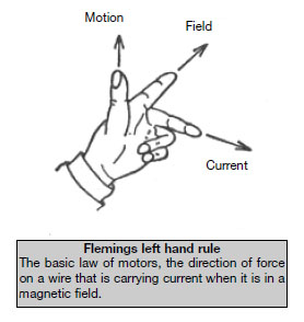
Direction of rotation is determined using Flemings Left Hand Rule.
• Point your First finger in the direction of the magnetic Field (from N to S).
• Rotate your hand about that finger until your second finger points in the direction of the Current (conventional current, from + to -).
• Then your thumb points in the direction of the Movement of the wire.
To increase the force on the wire (armature), do one of the following:
• Use a larger current.
• Use a stronger magnetic field.
• Use a greater length of wire in the field.
To increase torque and speed in the starter motor, more windings in the armature are added, and the field has more pairs of magnets (either permanent or electromagnetic).
Torque and speed of the starter motor is dependent on the wiring of the field coils. (electromagnetic coils)
• Shunt Wound • Series Wound • Compound
Shunt Wound Motors
In Shunt Wound Motors, the field coil is connected in parallel with the armature. The shunt motor does not decrease its
torque as speed increases. Shunt motors do not produce high torque.
Series Wound Motors
In Series Wound Motors, the field coil is in series with the armature.
The current flows to the field windings, then to the brushes, commutator, and armature back again to the ground side brush. A series wound motor will develop maximum torque output at the time of initial start, then as motor speed increases, torque falls off rapidly due to the CEMF.
Compound Wound Motors
Compound Wound Motors have some of the field coils wired in series to the armature and some in parallel. This configuration allows the compound motor to develop good starting torque and constant operating speed.
CEMF
Counter Electromotive Force
The voltage produced in the starter motor itself through electromagnetic induction.
This voltage acts against the supply voltage from the battery.
Motors must be designed to control the CEMF for optimum operation.
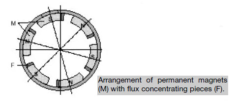
Permanent Magnet Motors
Permanent Magnet Motors eliminate all wiring to the field coils. The magnetic field is generated by the permanent magnet without the need for winding and pole shoes. The magnets use flux-concentrating pieces to direct the magnetic field.
Solenoid
The Solenoid performs the following functions:
• Pull the pinion to engage the flywheel
• Hold the pinion engaged with the flywheel during starting rotation.
• Complete the electrical circuit from the battery to the brushes of the starter.
• Cause the pinion to retract from the flywheel.
Two windings are used to pull and hold the pinion engaged to the flywheel.
Pull-In Winding - The stronger of the two windings, used to pull the pinion into engagement. This winding is released when the starter circuit is completed.
Hold-In Winding - Used to help the pull-in winding move the pinion initially, then holds the pinion engaged to the flywheel.
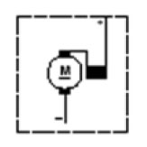
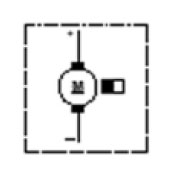
Signal 50 is received at the solenoid, energizing both windings. The windings cause the armature to be drawn into the coils, pressing on a spring, causing the moving contacts to close. The pull-in winding is released, the starter begins to turn. When signal 50 is released, the power is lost to the hold-in winding, spring pressure forces the armature out of the coil, the moving contacts are opened and the pinion returns to the rest position.
Workshop Hint
The starter motor does not begin to spin until after the pinion is engaged in the flywheel.
This aids in the meshing of the pinion and flywheel
Workshop Hint
Battery voltage is critical.
The combination of the pull-in winding and the hold-in winding may have sufficient power to engage the pinion. When the moving contacts are completed and the increased load of the starter motor is added to the system, low voltage will cause the hold-in winding to release the pinion. If signal 50 is still present the pull-in winding will again assist in pulling
the pinion into engagement and the cycle starts over again. This gives the “clicking” noise from the starter.
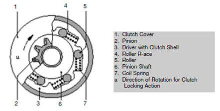
Pinion Drive
The Pinion Drive gear is attached to the roller-type overrunning clutch which is spun via a helical shaft to the starter armature. At rest the spring pressure in the overrunning clutch wedge rollers between the pinion shaft and the clutch hub race. This locks the pinion to the clutch. During start-up the clutch and pinion rotate as one.
As the engine speed exceeds starter speed, the pinion pushes the rollers, against the spring pressure, into a wider area. This movement of the rollers allow the pinion to turn independently of the starter armature, not causing the armature to overspeed. When the solenoid windings are released the clutch assembly is pulled away from the flywheel
through spring pressure.
Phases of Starter Operation
For more information on vehicle electrical systems, please check out the lots more information in RIBO Parts Articles. 


